1. Introduction
High-speed rail systems have become a cornerstone of modern transportation networks, demanding continuous advancements in track infrastructure to ensure safety, efficiency, and passenger comfort. Ballastless track, as an advanced track structure, has been extensively applied both domestically and internationally
. Compared to traditional ballasted track, it offers superior performance in terms of smoothness, stability, and durability
| [3] | Robertson I, Masson C, Sedran T, Barresi F, Caillau J, Keseljevic C, et al. Advantages of a new ballastless trackform. Construction and Building Materials, 2015, 92: 16–22. https://doi.org/10.1016/j.conbuildmat.2014.06.099 |
| [4] | Ren JJ, Deng SJ, Wei K, Li HL, Wang J. Mechanical property deterioration of the prefabricated concrete slab in mixed passenger and freight railway tracks. Construction and Building Materials, 2019, 208: 622–637. https://doi.org/10.1016/j.conbuildmat.2019.03.039 |
| [5] | Xu L, Yu ZW. Dynamic solution for vehicle-track interaction considering the elastoplasticity of track slabs. Journal of Vibration and Control, 2021, 27(13–14): 1668–1680. https://doi.org/10.1177/1077546320947295 |
| [6] | Xu QY, Wang X. Experimental study on high-cycle flexural fatigue behavior of cement mortar for ballastless track of high-speed railway. Construction and Building Materials, 2023, 385: 131525. https://doi.org/10.1016/j.conbuildmat.2023.131525 |
| [7] | Lu ZH, Wang J, Tang Z, Zhao YG, Li WG. A novel cohesive zone model for predicting the interface bonding behaviours of the ballastless track of high-speed railway. Structures, 2022, 41: 1–14. https://doi.org/10.1016/j.istruc.2022.04.082 |
[3-7]
. The China Railway Track System III slab track, a widely adopted solution for high-speed lines, plays a critical role in mitigating vibration and noise levels. However, the dynamic mechanical behavior of the CRTS III slab track, particularly its vibration-damping characteristics, remains a complex and crucial area of research. This paper presents a comprehensive analysis of the mechanical behavior of a novel vibration-damping CRTS III slab track, addressing key aspects that influence its performance and long-term reliability.
The interaction between the train, the track, and the underlying ground governs the generation and propagation of vibrations in high-speed rail systems. Research in this area focuses on characterizing the dynamic stiffness
and damping properties of the CRTS III slab track, as well as understanding how these properties influence vibration transmission
| [9] | OUAKKA S, VERLINDEN O, KOUROUSSIS G. Railway ground vibration and mitigation measures: benchmarking of best practices [M/OL] // Railway Engineering Science. Springer, 2022. https://doi.org/10.1007/s40534-021-00264-9 |
[9]
. Key areas of investigation include:
The contact forces between the wheel and the rail are the primary source of vibration excitation in the track
. Studies have explored the influence of wheel and rail profiles, as well as track irregularities, on the magnitude and frequency content of these forces
| [11] | ZENG Z, QAHTAN A A S, HU G, et al. Comparative experimental investigation of the vibration mitigation characteristics of ballasted track using the rubber composite sleeper and concrete sleeper under various interaction forces [J/OL]. Engineering Structures, 2023, 275: 115243. https://doi.org/10.1016/j.engstruct.2022.115243 |
[11]
. Vibrations generated at the wheel-rail interface propagate through the various components of the CRTS III slab track, including the rail, fasteners, slab, and supporting layers. Understanding the wave propagation
characteristics is essential for predicting vibration levels and designing effective damping solutions.
A portion of the track's vibration energy is transmitted to the surrounding ground, potentially causing noise and vibration issues in nearby buildings and communities
| [13] | LAKUŠIĆ S, HALADIN I, AHAC M. The effect of rail fastening system modifications on tram traffic noise and vibration [J/OL]. Shock and Vibration, 2016, 2016. https://doi.org/10.1155/2016/4671302 |
[13]
. Research in this area focuses on predicting ground-borne vibration levels and developing mitigation strategies
. Effective vibration damping is crucial for minimizing noise pollution, enhancing ride comfort, and ensuring the long-term integrity of the CRTS III slab track. Various damping mechanisms and mitigation strategies have been investigated, including:
The inherent damping properties of the track components, such as the concrete slab and rail pads
| [15] | KAEWUNRUEN S, REMENNIKOV A. Laboratory measurements of dynamic properties of rail pads under incremental preload [J]. Faculty of Engineering - Papers, 2006. |
[15]
, contribute to the overall vibration reduction. Research has focused on characterizing these material properties and exploring ways to enhance their damping capacity.
Friction between the various track components can dissipate vibration energy. Studies have investigated the role of friction damping in CRTS III slab tracks and explored ways to optimize its effectiveness
| [16] | CHEN W, LI S, WANG W, et al. Analysis on crack propagation of CRTS III slab ballastless track under temperature loads and freeze–thaw deterioration [J]. Theoretical and Applied Fracture Mechanics, 2024, 129: 104206. |
[16]
. These devices can be strategically placed on the track to absorb vibration energy at specific frequencies. Research has explored the design and implementation of tuned mass dampers for CRTS III slab tracks. Introducing damping layers beneath the track slab can effectively reduce vibration transmission to the underlying ground
| [17] | HUANG X, LI P, LUO X, et al. Performance Analysis of Prefabricated Steel-Spring Floating-Slab Track and Its Application to Urban Express Rail Transit [J/OL]. Advances in Civil Engineering, 2020, 2020. https://doi.org/10.1155/2020/4515319 |
[17]
. Studies have investigated the performance of various damping materials and their long-term effectiveness.
Existing literature has explored various facets of CRTS III slab track behavior. Studies like
have investigated the vibration properties of slab tracks on viaducts, comparing CRTS II
| [18] | DAI F, THOMPSON D J, ZHU Y, et al. Vibration properties of slab track installed on a viaduct [J]. Proceedings of the Institution of Mechanical Engineers, Part F: Journal of Rail and Rapid Transit, 2016, 230(1): 235-252. |
[18]
and floating slab track designs using analytical models. The dynamic characteristics of concrete floating slab tracks
| [19] | ZHANG X Y, LU Z H, ZHAO Y G, et al. Reliability analysis of CRTS II track slab considering multiple failure modes [J]. Engineering Structures, 2021, 228: 111557. |
[19]
in urban environments have been examined using finite element analysis
| [20] | ZHI-PING Z, JUN-DONG W, SHI-WEN S, et al. Experimental study on evolution of mechanical properties of CRTS III ballastless slab track under fatigue load [J]. Construction and Building Materials, 2019, 210: 639-649. |
[20]
, considering factors such as train speed, stiffness, and damping
| [21] | LIANG G, YIN K M, ZHANG G Y. Study on dynamics characteristics of concrete floating slab track in urban track [J]. Key Engineering Materials, 2005, 302: 700-705. |
[21]
. Further, it explores the vibration characteristics of floating slab tracks and their impact on train dynamics. The application and long-term effects of vibration reduction measures in CRTS III slab track have been investigated through field measurements and time-frequency analysis
| [22] | KUO C M, HUANG C H, CHEN Y Y. Vibration characteristics of floating slab track [J]. Journal of Sound and Vibration, 2008, 317(3-5): 1017-1034. |
[22]
.
The long-term performance and reliability of the CRTS III slab track are paramount. Investigates the dynamic performance under long-term service conditions, considering factors like fatigue and potential parting between the track slab and self-compacting concrete. Reliability analysis of CRTS II track slabs, considering multiple failure modes as discussed, can inform similar analyses for CRTS III. Furthermore, the dynamic responses of the vehicle-CRTS III slab track system under seismic excitation, provide insights into its behavior under extreme events
| [23] | WANG Q, CAI X, TANG X, et al. Application and long-term effects of vibration reduction in CRTSIII slab track: Insights from field measurements [J]. Soil Dynamics and Earthquake Engineering, 2024, 179: 108518. |
| [24] | LOU P, GONG K, ZHAO C, et al. Dynamic Responses of Vehicle-CRTS III Slab Track System and Vehicle Running Safety Subjected to Uniform Seismic Excitation [J]. Shock and Vibration, 2019, 2019(1): 5308209. |
| [25] | GUO W, WANG Y, LIU H, et al. Seismic safety assessment of trains running on high-speed railway bridges with chloride-induced corroding piers [J/OL]. Science China Technological Sciences, 2023, 66(2): 320-335. https://doi.org/10.1007/s11431-022-2193-x |
[23-25]
.
Despite significant advancements in CRTS III slab track technology, several challenges remain, including The long-term durability and effectiveness of vibration damping systems in CRTS III slab tracks need to be further investigated
| [26] | BORJIGIN S, KIM C W, CHANG K C, et al. Nonlinear dynamic response analysis of vehicle–bridge interactive system under strong earthquakes [J/OL]. Engineering Structures, 2018, 176: 500-521. https://doi.org/10.1016/j.engstruct.2018.09.014 |
[26]
, considering factors such as environmental degradation and fatigue. Developing cost-effective vibration-damping solutions is crucial for widespread implementation. Optimizing the design
| [27] | Liu, C. X.; Zhai, W. M. Elementary research on problem of slab’s intensity by means of finite element analysis. J. Railw. Eng. Soc. 2001, 1, 24–26. (In Chinese) |
[27]
and placement of damping systems to achieve maximum vibration reduction remains an active area of research. This paper addresses this gap by presenting a novel approach to vibration damping in the CRTS III slab track. We delve into the underlying mechanisms of the proposed technique and its impact on the track's mechanical behavior. A detailed analysis, incorporating numerical simulation validation, is presented to demonstrate the effectiveness of the proposed solution. The findings of this study contribute to the ongoing development of high-performance CRTS III slab track systems, paving the way for enhanced ride comfort, reduced noise pollution, and improved long-term structural integrity. The subsequent sections of this paper will detail the methodology, results, and discussions of our investigation. Through the research conducted in this paper, a comprehensive understanding of the systematic analysis of the mechanical behavior of a novel vibration-damping CRTS III (VDT) track slab using a three-dimensional finite element model was achieved. The inclusion of vibration isolation pads beneath the self-compacting concrete (SCC) layer significantly reduces the natural frequencies of the VDT track compared to the conventional CRTS III track. Modal analyses reveal that the vibration-damping performance of the VDT track effectively mitigates noise and vibration. However, the weaker support provided by the vibration isolation pads renders the VDT track more vulnerable to train loads and thermal gradient loads.
2. Numerical Simulation
2.1. Specification of New Track Structure
The The vibration-damping track (VDT), as illustrated in
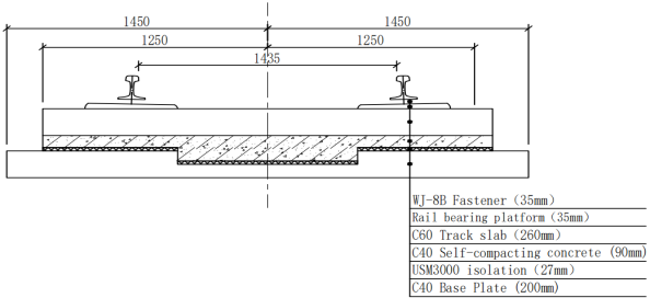
Figure 1, shares a structural composition with the CRTS III slab track, consisting of rails, fasteners, track slabs, self-compacting concrete, and base plates. To enhance its vibration mitigation capabilities, an additional layer of rubber vibration-damping pads is introduced. The structural components, including the track slab, self-compacting concrete, and base plate, are unitized. The track slab has dimensions of 2500 mm in width, 200 mm in thickness, and 5600 mm in length, while the self-compacting concrete layer is 90 mm thick. The base plate is 2900 mm wide, 200 mm thick, and is equipped with expansion joints between adjacent units, filled with polyethylene foam boards. The total height of the track system, measured from the top of the rail to the base plate’s bottom, is 765 mm. The track slab is constrained laterally by the convex platform of the base plate.
Figure 1. Structure of vibration-damping track (VDT).
On the top surface of the base plate, point-supported rubber isolation pads are installed. These pads are 27 mm thick, and for the analysis, the USM3000 rubber isolation pad was selected, offering an elasticity modulus of 1.05 MPa based on its prevalent application in engineering. Reducing the stiffness of the vibration isolation pads helps lower the base plate’s acceleration, achieving effective vibration damping. However, this reduction also leads to increased dynamic responses in the rail and track slab, such as higher displacements and accelerations. To achieve a balanced performance between vibration damping and track system stability, a moderate stiffness of 0.030 N/mm3 or the vibration isolation pads was determined to be optimal.
The low-stiffness rubber vibration-damping pad is a crucial component in the ballastless CRTS III slab track system. It provides elasticity to the track structure, reduces system stiffness, and significantly improves vibration mitigation performance.
2.2. Establishment of a Finite Element Model
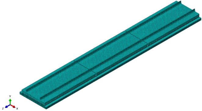
A Finite Element Model of VDT was established using ABAQUS/CAE, which mainly consists of rails, fasteners, track slabs, filling layers, isolation pads, and base plates. To minimize the impact of boundary conditions, the model length is set to the length corresponding to three track slabs. During the analysis, the central track slab is selected for evaluation. The model parameters are provided in
Table 1, and the overall track slab model is shown in
Figure 2.
Table 1. Numerical simulation parameters.
Name | Elastic modulus (MPa) | Poisson ratio | Density (kg/m3) | Expansion coefficient (10-5/°C) |
Rail | 206000 | 0.3 | 7850 | 1.18 |
Slab | 36000 | 0.2 | 2500 | 1.0 |
SCC | 32500 | 0.2 | 2500 | 1.0 |
BP | 32500 | 0.2 | 2500 | 1.0 |
Figure 2. Finite element model of VDT.
The rails are standard CHN60 rails, the track slabs are made of C60 concrete, and the base plates (BP) are made of C40 concrete. The filling layer is a type of self-compacting concrete (SCC). Below the filling layer, there are two square protrusions that fit into corresponding grooves on the base plate, serving to restrict the longitudinal and lateral free movement of the track slabs. All these components are modeled using 8-node linear hexahedral elements (C3D8R). It is important to note that, to reduce the collision effects, an elastic padding layer is placed around the protrusions in reality. Therefore, the contact between the square protrusions and the base plate grooves is simulated using an equivalent stiffness approach, with an equivalent stiffness of 3 N/mm³, without considering the friction coefficient. Similarly, the vibration isolation pads are also modeled using the equivalent stiffness method. The vertical contact stiffness between the filling layer and the base plate is 0.030 N/mm³, but the interaction in the horizontal direction is considered. Hence, a friction coefficient of 0.6 is applied. The fasteners are modeled using springs in three directions. The vertical stiffness is 35 kN/mm, the horizontal stiffness is 40 kN/mm, and the longitudinal stiffness is nonlinear, as specified in Equation (
1).
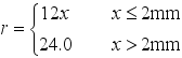 (1)
(1) Where

represents the longitudinal resistance of the fastening system, expressed in kN/ (m·rail);

denotes the longitudinal displacement of the rail relative to the fastening system, measured in millimeters (mm).
For the boundary conditions, the longitudinal and lateral degrees of freedom at both ends of the rail are constrained. A support stiffness of 1200 MPa/m is applied at the bottom of the base plate to simulate the support provided by the track bearing layer.
3. Modal Analysis
To investigate the vibration-damping performance of the VDT, this section calculates its mode shapes and natural frequencies based on modal analysis theory. A detailed comparison with the modal characteristics of the traditional CRTS III slab track is conducted to reveal the underlying vibration-damping mechanism.
3.1. Principles of Modal Analysis
Modal properties are fundamental characteristics of structural systems, reflecting their inherent dynamic behavior. Modal analysis is a crucial tool for evaluating the vibration characteristics of a structure, including its natural frequencies and corresponding mode shapes. In railway track design, this analysis is indispensable for preventing resonance between the train and the track system, which could otherwise accelerate fatigue and compromise the structural integrity of the track. By mitigating such risks, modal analysis significantly contributes to extending the service life of the track structure. Moreover, it serves as an effective method for assessing the performance of track systems and diagnosing potential structural damage.
Natural frequencies of track systems are particularly vital, as they provide critical insights for optimizing track design. The multi-layered structure of railway tracks can be modeled as a linear elastic system with n degrees of freedom, governed by the following vibration equation (
2):
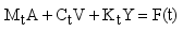 (2)
(2) Where

is quality matrix of a multi-layer system of tracks;

is damping matrix of a multi-layer system of tracks;

is stiffness matrix of a multi-layer system of tracks; is

acceleration matrix of a multi-layer system of tracks;

is velocity matrix of a multi-layer system of tracks;

is displacement matrix of a multi-layer system of tracks;

is the matrix of the external excitation.
While the damped natural frequency (

) is related to the undamped frequency (

) and the damping ratio (

) by equation (
3):
 (3)
(3) For most structures, the damping ratio is relatively small. When calculating the natural frequencies of the track system, the vibration can be simplified as undamped. The simplified undamped vibration equation is expressed as Equation (
4).
 (4)
(4) 3.2. Comparison of Modal Features
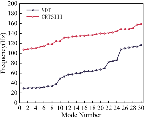
Figure 3 presents a comparison of the first 30 natural frequencies between the VDT and traditional CRTS III track systems. As shown, the VDT system exhibits a significant reduction in its natural frequencies compared to the traditional CRTS III track. Specifically, the first six natural frequencies of the VDT system range from 29 to 32 Hz, while the corresponding frequencies for the CRTS III track range from 107 to 114 Hz. This results in a reduction of up to 78 Hz in the VDT system’s natural frequencies, indicating its potential to effectively mitigate low-frequency vibrations transmitted to the foundation.
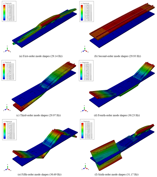
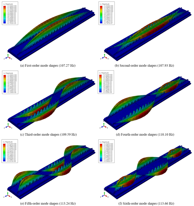
Figures 4 and 5 illustrate the first six vibration modes of the VDT and CRTS III track systems, respectively. The modal analysis reveals that the vibration characteristics of these two track types differ significantly.
For the VDT system:
Mode 1: The primary motion is a rotational movement of the rail, slab, and self-compacting concrete layer (composite slab) about the longitudinal axis, with a frequency of 29.14 Hz.
Mode 2: The system exhibits vertical translation of the rail and composite slab as a whole, with a frequency of 29.93 Hz.
Mode 3: The primary motion is rotational movement about the transverse axis, with a frequency of 29.97 Hz.
Mode 4: Vertical bending of the rail and composite slab dominates, with a frequency of 30.23 Hz.
Mode 5: Secondary vertical bending of the rail and composite slab is observed, with a frequency of 30.69 Hz.
Mode 6: A torsional motion of the rail combined with rotational movement of the composite slab about the longitudinal axis occurs, with a frequency of 31.17 Hz.
For the CRTS III system:
Mode 1: The rail undergoes lateral bending, with a frequency of 107.27 Hz.
Mode 2: Opposing lateral bending of the left and right rails is observed, with a frequency of 107.93 Hz.
Mode 3: Both rails exhibit synchronized second-order lateral bending, with a frequency of 109.59 Hz.
Mode 4: Opposing second-order lateral bending of the left and right rails is seen, with a frequency of 110.10 Hz.
Mode 5: The rails exhibit synchronized third-order lateral bending, with a frequency of 113.24 Hz.
Mode 6: Opposing third-order lateral bending of the left and right rails dominates, with a frequency of 113.66 Hz.
Figure 3. Comparison of natural frequencies.
Figure 4. The first six mode shapes of VDT.
Figure 5. The first six mode shapes of CRTS III.
A comparative analysis of the first six vibration modes of the VDT and CRTS III systems reveals key distinctions in their dynamic behavior. The VDT system primarily exhibits low-frequency vibrations involving the rail and composite slab as an integrated system. These modes facilitate significant energy dissipation of vibrations induced by train operation, effectively reducing the transmission of vibrations to the base structure. Consequently, the VDT system achieves effective vibration isolation and noise reduction, particularly within the low-frequency range. In contrast, the CRTS III system's vibration modes are predominantly characterized by the independent motion of the rails, with minimal mass involved in the vibration. The modes mainly comprise lateral oscillations at higher frequencies, which are less effective at attenuating the vertical vibrations transmitted from the train to the base. This limits the CRTS III system's ability to mitigate vibration and noise effectively.
4. Mechanical Behavior Under Load
The design of ballastless tracks must comprehensively address train loads, thermal loads, and the effects of subgrade settlement. Among these factors, vertical train loads have the most pronounced impact on the track system in straight sections, whereas lateral loads are relatively less significant in such configurations. The VRT track system analyzed in this study is specifically designed for straight sections in station areas, where the presence of a load-bearing layer beneath the track slab substantially mitigates the influence of subgrade settlement. Additionally, among thermal loads, the temperature gradient load exerts the greatest influence on the track's performance. Therefore, this section emphasizes the mechanical behavior of the VRT track under vertical train loads and temperature gradient loads. It should be noted that the self-weight of the track system is included in all load scenarios analyzed in this study.
4.1. Mechanical Behavior Under Vertical Load of the Train
4.1.1. Load Conditions
The quasi-static calculation method is widely utilized to evaluate wheelset loads. This method applies the fundamental principles of static analysis to the track structure while incorporating the dynamic characteristics of the wheel-rail system. The dynamic impact is then simplified as an incremental effect on the wheel load
| [27] | Liu, C. X.; Zhai, W. M. Elementary research on problem of slab’s intensity by means of finite element analysis. J. Railw. Eng. Soc. 2001, 1, 24–26. (In Chinese) |
| [28] | Zeng, Z. P.; He, X. D.; Huang, X. D.; Wang, W. D.; Wang, D.; Qahtan, A. A. S.; Boumedienne, H. S. Numerical simulation research on mechanical optimization of a novel fastener type ballastless track (NFTBT) for tram. Appl. Sci. 2022, 12, 8807. |
[27, 28]
. Globally, many countries adopt the speed coefficient method to determine the vertical load of trains, which accounts for the dynamic interaction between wheels and rails, resulting in an increased wheel load
| [29] | Chen, X. F.; Lou, P. Railway Engineering, 2nd ed.; China Architecture & Building Press: Beijing, China, 2017; pp. 210–213. (In Chinese) |
[29]
. However, the specific value of the speed coefficient varies across different countries.
In this study, the commonly used formula for calculating the vertical dynamic wheel load in China is adopted, as presented in Equation (
5)
| [30] | Zhang, P. F.; Luo, K. Railway Track Engineering; Central South University Press: Changsha, China, 2017; pp. 144–155. (In Chinese) |
[30]
.
 (5)
(5) where

is vertical dynamic wheel load;

is the static wheel load, the train axle weight is 17 t, and the single-strand rail static wheel load is 8.5 t;

is the dynamic load coefficient, it represents the relationship between train speed and the increased dynamic effect on the wheel-rail system. For the design speed of 300 km/h considered in this study, the value of

is determined based on the Chinese railway standard, which specifies a coefficient of 3.0 for this operating speed. In summary, the train vertical load used for the finite element model calculation is 255 kN.
And the study focuses on two loading scenarios: the first corresponds to the position where the load is applied to the middle of the track slab, aligned with the steel rail; the second corresponds to the position where the load is applied to the end of the track slab, aligned with the steel rail.
4.1.2. Comparison of the Results
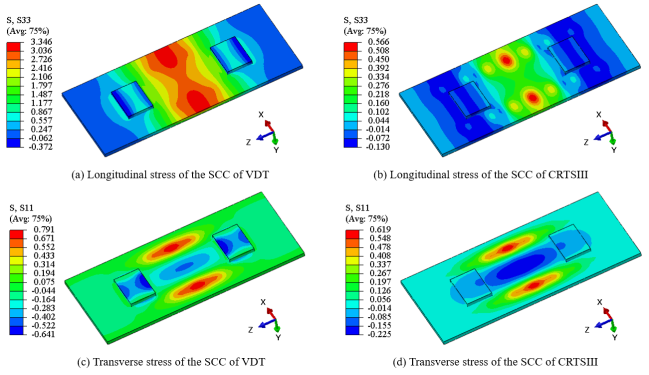
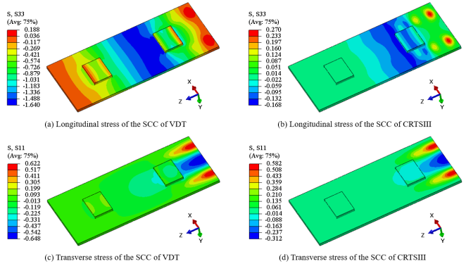
Figure 6 shows the stress distribution of the SCC in two types of track structures when the load is applied at the middle of the slab, while
Figure 7 presents the stress distribution when the load is applied at the end of the slab. It is evident that the compressive stress in the SCC of the VDT track is significantly higher than that in the SCC of the CRTSIII track. However, regardless of whether the load is applied at the middle or the end of the slab, the compressive stresses are well below the compressive strength of concrete. Therefore, when analyzing the most unfavorable loading position, compressive stress should not be the primary indicator. Instead, the tensile stress in the concrete should be considered. When the load is applied at the middle of the slab, the tensile stress in the SCC is higher compared to when the load is applied at the end of the slab. Thus, for the SCC, the load position at the middle of the slab is more detrimental.
Figure 6. Stress distribution of the SCC of the two tracks when the load acts on the middle of the slab.
Figure 7. Stress distribution of the SCC of the two tracks when the load acts on the end of the slab.
From
Figure 6, it can be observed that, theoretically, the maximum longitudinal tensile stress in the SCC of the VDT track is 3.346 MPa, whereas for the CRTSIII track, it is 0.566 MPa. The maximum transverse tensile stress in the SCC of the VDT track is 0.791 MPa, compared to 0.619 MPa for the CRTSIII track. The longitudinal tensile stress in the SCC of the VDT track is 491.2% higher than that in the CRTSIII track, while the transverse tensile stress is 27.8% higher. This indicates that the SCC of the VDT track requires more tensile reinforcement, especially longitudinal reinforcement.
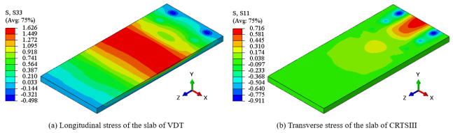
In the calculations, it was found that the tensile stress in the track slab is higher when the load is applied at the end of the slab. Therefore, the most unfavorable loading position for the track slab occurs when the load acts at the slab's end. Additionally, the stress distribution in the track slabs of both track structures is similar under different loading positions, with only the magnitudes differing. Due to space limitations, only the stress distribution of the VDT track slab when the load is applied at the end of the slab is presented, as shown in
Figure 8. The maximum longitudinal tensile stress occurs at the center of the track slab's top surface, while the maximum transverse tensile stress is located at the central part of the upper surface at the load application point. The maximum longitudinal tensile stress in the VDT track slab is 1.626 MPa, compared to 0.222 MPa in the CRTSIII track slab. The maximum transverse tensile stress in the VDT track slab is 0.716 MPa, compared to 0.284 MPa in the CRTSIII track slab. The longitudinal tensile stress in the VDT track slab is 632.4.7% higher than that in the CRTSIII track slab, and the transverse tensile stress is 152.1% higher. This indicates that the VDT track slab requires more tensile reinforcement, especially longitudinal reinforcement.
Figure 8. Stress distribution of slab of the two tracks when the load acts on the end of the slab.
4.2. Mechanical Behavior Under Temperature Gradient
4.2.1. Temperature Gradient Conditions
The temperature gradient in track structures generally exists within a thickness range of 0.2 meters. Therefore, a linear temperature gradient load is applied to the track slab structure with a thickness of 0.2 meters in the model, while other components are assumed to have no temperature gradient. According to Chinese design codes for track structures, the positive temperature gradient is taken as 90°C/m and the negative temperature gradient as -45°C/m. For conservatism, in this study, the positive temperature gradient is taken as 100°C/m and the negative temperature gradient as -50°C/m.
4.2.2. Comparison of Results Under a Positive Temperature Gradient
Under the action of a positive temperature gradient, the track slab exhibits upward arching deformation at the center of the slab, leading to unfavorable tensile stresses in the track structure.
Table 2 summarizes the stress and displacement results of the VDT and CRTSIII track structures under positive temperature gradient loading. In this table, positive stress indicates tensile stress, while negative stress indicates compressive stress; positive vertical displacement indicates upward movement, and negative vertical displacement indicates downward movement.
Table 2. Comparison of stress and displacement in track structures under a positive temperature gradient of 100°C/m.
Structure | Type | Stress (MPa) | Displacement (mm) |
Longitudinal | Transverse | Longitudinal | Transverse | Vertical |
Slab | VDT | 1.545/-2.611 | 1.652/-1.346 | 0.398 | 0.233 | 0.854/-1.366 |
CRTSIII | 1.558/-3.034 | 1.646/-1.540 | 0.374 | 0.235 | 1.583/-0.235 |
SCC | VDT | 1.716/-1.218 | 1.537/-2.443 | 0.117 | 0.058 | 0.834/-1.364 |
CRTSIII | 1.882/-1.094 | 1.516/-2.353 | 0.130 | 0.060 | 1.563/-0.231 |
The results show that under the positive temperature gradient load, the compressive stresses in the track slab and SCC of both track structures are far below the compressive strength of concrete. The longitudinal and transverse tensile stresses in the track slab and SCC of the VDT structure are not significantly different from those in the CRTSIII structure. Similarly, horizontal displacements are also comparable between the two structures. However, there is a notable difference in vertical displacements.
This difference can be attributed to the behavior of the track slab under a positive temperature gradient, where the composite slab tends to arch upward at the center while its four corners exhibit a downward movement. For the VDT structure, the lower part of the SCC is supported by a low-stiffness vibration isolation layer, which provides softer support to the composite slab. As a result, the four corners of the composite slab can settle more freely. Even if the relative vertical displacement between the center and the corners of the slab remains unchanged, the absolute upward arching at the center is reduced due to the overall settlement of the composite slab driven by the corner settlements.
The deformation of the track slab inevitably induces deformation in the rail.
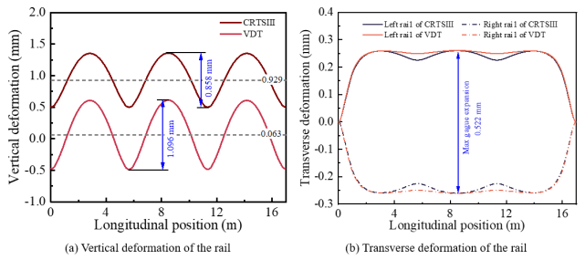
Figure 9 illustrates the deformation characteristics of the rail in VDT and CRTSIII track structures under a positive temperature gradient load. Specifically,
Figure 9(a) shows the vertical displacement of the rail top surface, while
Figure 9(b) presents the lateral displacement at a point 16 mm below the rail top on the inner side, corresponding to the gauge measurement position in Chinese railway standards.
Figure 9. Rail deformation at a positive temperature gradient of 100°C/m.
As shown in
Figure 9(a), the positive temperature gradient load causes a quasi-cosine-shaped vertical irregularity in the rail. The irregularity wavelength matches the length of a single track slab (5.67 m), and its amplitude is influenced by the track structure and temperature gradient magnitude. Under a positive temperature gradient of 100°C/m, the VDT rail exhibits a vertical irregularity amplitude of 1.069 mm, exceeding the CRTSIII rail's amplitude of 0.858 mm. Furthermore, the CRTSIII rail shows a greater absolute vertical displacement, with the irregularity baseline deviating 0.929 mm from the design reference plane, compared to just 0.063 mm for the VDT rail. This indicates that a specially designed transition section is necessary between the CRTSIII track and the VDT track to mitigate the vertical deformation difference of the rails under the influence of a temperature gradient. Such a design would enhance the smoothness of the railway line.
When analyzing
Figure 9(b), it is important to focus on the data within the longitudinal range of 5–12 m, as the boundary conditions influence the results of other positions. From
Figure 9(b), it is evident that the positive temperature gradient causes gauge expansion, resulting in a quasi-cosine-shaped gauge irregularity. However, the amplitude of this irregularity is minimal for both track structures, having a negligible impact on operational safety. Under a positive temperature gradient of 100°C/m, the maximum gauge expansion for both track structures is identical, measuring 0.522 mm.
4.2.3. Comparison of Results Under a Negative Temperature Gradient
Under the influence of a negative temperature gradient, the track slab undergoes deformation characterized by upward curling at the corners, resulting in unfavorable tensile stresses within the track structure.
Table 3 presents the stress and displacement results for the VDT and CRTSIII track structures under the negative temperature gradient load. In the table, positive stresses indicate tensile stress, negative stresses indicate compressive stress, while positive vertical displacements correspond to upward movement and negative displacements to downward movement.
Table 3. Comparison of stress and displacement in track structures under a negative temperature gradient of -50°C/m.
Structure | Type | Stress (MPa) | Displacement (mm) |
Longitudinal | Transverse | Longitudinal | Transverse | Vertical |
Slab | VDT | 1.358/-0.776 | 0.688/-0.830 | 0.200 | 0.116 | 0.779/-0.320 |
CRTSIII | 2.017/-0.918 | 1.206/-0.824 | 0.187 | 0.113 | 0.809/-0.056 |
SCC | VDT | 0.621/-0.858 | 1.190/-0.776 | 0.059 | 0.029 | 0.778/-0.310 |
CRTSIII | 0.628/-1.207 | 1.095/-0.795 | 0.063 | 0.025 | 0.808/-0.046 |
From the table, it is evident that under the negative temperature gradient load, the compressive stresses in the track slab and SCC of both track structures remain similarly low. The longitudinal and transverse tensile stresses in the VDT track slab are lower than those in the CRTSIII track slab. The stresses in the SCC of both track structures are nearly identical, and the differences in horizontal displacement are negligible. Additionally, the absolute value of the upward curling at the slab corners is also quite similar between the two track structures.
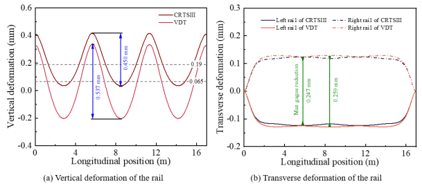
Figure 10 illustrates the deformation characteristics of the rail in VDT and CRTSIII track structures under the negative temperature gradient load. As shown in
Figure 10(a), the negative temperature gradient induces rail irregularities with a wavelength equal to the length of the track slab unit. Under a -50°C/m temperature gradient, the amplitudes of the rail irregularities in the VDT and CRTSIII tracks are similar, measuring 0.537 mm and 0.450 mm, respectively, with the baseline positions of the irregularities deviating from the design reference plane by less than 0.2 mm.
Figure 10(b) shows that the negative temperature gradient causes a reduction in track gauge, with the reduction being nearly identical for both track structures—0.259 mm for VDT and 0.247 mm for CRTSIII. Therefore, the negative temperature gradient has a negligible effect on rail irregularities for both track structures.
Figure 10. Rail deformation at a positive temperature gradient of 100°C/m.
5. Conclusion
This study conducts a systematic analysis of the mechanical behavior of a novel vibration-damping CRTS III (VDT) track slab using a three-dimensional finite element model. The inclusion of vibration isolation pads beneath the self-compacting concrete (SCC) layer significantly reduces the natural frequencies of the VDT track compared to the conventional CRTS III track. Modal analyses reveal that the vibration-damping performance of the VDT track effectively mitigates noise and vibration. However, the weaker support provided by the vibration isolation pads renders the VDT track more vulnerable to train loads and thermal gradient loads. Key findings are summarized as follows:
1) The VDT track exhibits natural frequencies in the range of 29-32 Hz for the first six modes, significantly lower than the 107-114 Hz observed in the CRTS III track.
2) The primary modes of the VDT track involve low-frequency vibrations of the rail and composite slab, facilitating energy dissipation and noise reduction in the low-frequency domain. In contrast, CRTS III track modes predominantly involve rail vibrations with limited energy dissipation capabilities.
3) When a vertical train load is applied at the mid-span of the slab, the longitudinal tensile stress in the SCC layer of the VDT track is 491.2% higher than that in the CRTS III track, and transverse tensile stress is 27.8% higher. This indicates a need for enhanced longitudinal reinforcement in the SCC layer of the VDT track.
4) Under vertical train loads applied at the slab ends, the longitudinal tensile stress in the VDT slab is 632.4% higher, and the transverse tensile stress is 152.1% higher than in the CRTS III slab. This underscores the necessity for stronger longitudinal and transverse reinforcements in the VDT slab.
5) Positive Temperature Gradient Load (100°C/m): The tensile stresses in both the SCC layer and track slab for VDT and CRTS III tracks show no significant differences. However, the vertical displacement of the VDT track slab arching is markedly reduced compared to the CRTS III track.
6) Negative Temperature Gradient Load (-50°C/m): The tensile stresses in the SCC layer are nearly identical for both track types. Interestingly, the longitudinal and transverse tensile stresses in the VDT slab are lower than those in the CRTS III slab. Horizontal and vertical displacements are comparable for both tracks.
7) Track Irregularities: Temperature gradients induce wavelength-scale vertical irregularities in the rail. Under a positive gradient of 100°C/m, the vertical irregularity amplitude in the VDT rail is 1.069 mm, exceeding the 0.858 mm in the CRTS III rail. For a negative gradient of -50°C/m, the amplitudes are similar, at 0.537 mm (VDT) and 0.450 mm (CRTS III).
8) Gauge Expansion: Positive temperature gradients lead to slight gauge expansions, while negative gradients result in minor gauge reductions. Under a positive gradient of 100°C/m, the maximum gauge expansion for both track types is approximately 0.522 mm. Under a -50°C/m gradient, gauge reductions are 0.259 mm (VDT) and 0.247 mm (CRTS III).
9) A specially designed transition section is necessary between the CRTS III and VDT tracks, as the vertical displacement differences of the rail under positive temperature gradients can lead to operational discontinuities.